


When we think of an LED optic, we tend to think of a clear plastic lens that is placed on top of the LED itself to focus or spread the light. If this is your thought process, you’ve gone too far.  Lets take a step back and look at the LED itself. See that small protective dome over the diode? That is actually called the primary optic which serves to protect and shape the output of the small diode. The light from the LEDs primary optic is still too broad for most applications, lacking intensity over distance. This is why most LED fixtures use secondary optics (lenses, reflectors, TIR optics, etc.) to collect all that light and magnify its intensity towards the target.
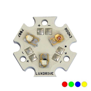
Creating lenses and reflectors for LEDs (solid-state lighting) is much different than just scaling 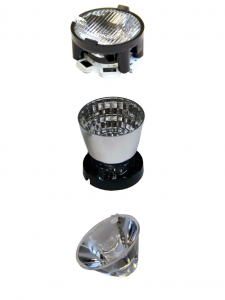 them down from other light sources. This might seem like a logical way of creating them, as LEDs have much smaller form factors than other light sources, but they also differ in how they emit the light. As you can see from incandescent bulbs, they illuminate in 360 degrees, but LEDs are directional lighting, illuminating only 180 degrees. This is attributed to the design of an LED, as you can see to the left, a light emitting diode consists of one or more die, mounted on a heat-conducting material, with the primary optic enclosing the die. Therefore, the maximum angle LEDs can emit is 180 degrees as the substrate is on the back side of the die.
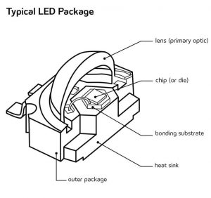
The Primary Optic
Typical spatial distribution is what manufacturers use to describe the light coming from an LEDs primary optic. This basically means the shape or spread of the light from the center of the diode. As we talked about earlier, LEDs face in one direction, so imagine a line running straight down from the center. Spatial distribution is measured in degrees from this center point.
Let’s take the Cree XP-G2 for example, which is rated at 115 degrees, meaning the beam will extend 57.5 degrees on either side. Just because it is rated for this, does not mean you get the entire lumen output of the LED across the whole spectrum. The light will be stronger the closer you are to the center, like other point of light sources. Take a look at the ‘Typical Spatial Distribution’ graph of the XP-G2, a graph like this will be on the emitters data sheets, which can be found on all LED product pages on the site.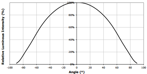
Along the center axis, the LED emits 100% of its relative luminous intensity and will lose intensity the farther away you move from the center. Say we are running a Cool White Cree XP-G2 at 350mA, we know from the data sheets that at this drive current, the LED will give off 139 Lumens, it’s rated output, at the central axis. At 30 degrees from center, the output of the LED drops to 125 Lumens. Going down the distribution curve at 40 degrees, the output reaches only 111 Lumens. This continues to drop until at 57.5 degrees you are only getting about half the lumen output at 70. It is obvious when you are losing this much light output over the spectrum, that a secondary lens or optic is needed to intensify that light and use the brightness and efficiency of LEDs to their full capacity.
LEDs Need to Focus
High power LEDs are constantly improving and becoming smart options for a wide range of applications. As we have stated above, for a lot of these applications, such as interior spot/down lighting, street lighting, architectural lighting and spot lighting, the emitter and primary optic on their own cannot deliver enough intensity to the target surface. We dove into emitters output above but another way of describing it is that emitters give off a Lambertian light distribution. This basically means that the brightness to an observer is the same, regardless of the observers position. If you have ever seen a bare emitter light up, you can see this instantly. Even if you are far to the side, you can still see that the light source is extremely bright, it will probably even bother your eyes to look at. The problem is that this light is just thrown out there with nothing harnessing the rays.
Secondary optics are used to collimate the light rays into a controlled beam that will bring that full intensity to the area you need. Collimated light rays spread in parallel, although it is impossible to make the light perfectly parallel because of diffraction and the finite physical size of the bare emitter. It is important to note that the smaller the light source (emitter), the more effective the process will be.
In describing how a certain secondary optic or lens can collimate a beam, we often look at the viewing angle or full width half maximum (FWHM). FWHM is the angular width of the beam when the intensity at the edge is half the intensity in the center of the beam. This is a helpful way to classify optics, but it doesn’t take into account the differences between certain optical platforms (different sized diodes). It is good to know that optics with identical viewing angles can differ quite a lot in intensity and quality of the beam depending on the emitters optical design. On the optics pages on our site, we try to list all the different angles and FWHM for each LED we carry.
Secondary optics are not only made to collimate the light, sometimes they are used to improve color uniformity and light distribution within the targeted area. Choosing the appropriate optic or lens depends on the application. Reflectors and TIR optics are used in many different applications and both have advantages and disadvantages.
Reflectors are easier to implement and cost much less to manufacture than TIR optics. How well they collect and collimate the light depends on their shape. Sometimes they are also used with different finishes to add a texture to the light or diffuse it. Often the physical size of light sources limit the optical options. With chip-on board (COB) arrays or emitters, they emit such a large area that the only real solution is to surround them with a reflector.
Reflectors are used in the majority of incandescent lights, but with LEDs there is one key disadvantage: the majority of light rays coming from the center of the emitter pass out of the system without even touching the reflector. This means that even with a narrow reflective system, a significant portion of the light strays wide of the target. This results in lost lumen output or creates an unwanted glare.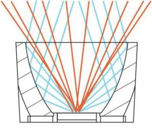
This is why it has become common, especially with the improvements on high lumen-density emitters, to envelope it in a TIR lens to guide pretty much all of the light toward the target.
Total Internal Reflection (TIR) optics, or lenses, are generally injection molded from polymers and use a refractive lens inside a reflector. They are typically cone shaped and can have very high efficiencies in reflecting and controlling the LEDs light spread. They typically work so that the lens directs light from the 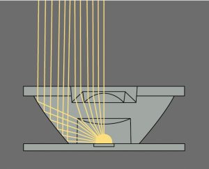 center of the emitter to the reflector, which then sends it out in a collimated and controlled beam, whether narrow, wide, whatever your choice.
There is an additional surface over the assembly that provides more opportunity to modify the light. These surface treatments (ripple, frosted, polished, etc.) diffuse the light, widen the beam or shape the distribution.
 TIR optics really work well with LEDs as they take advantage of emitters characteristics. Other forms of light radiate heat outward, whereas LEDs send heat out their base which allows these TIR optics to fit snug and totally surround the domed top. This allows a lot more control as they are illuminating and controlling literally straight from the light source.
TIR Optics are used a lot in outdoor lighting and have made big steps in indoor applications as well. They are ideal for narrow beam control but don’t work as well when emphasis is on diffused light and low glare.
Size Matters
The ratio of size of an LED to the size of the optic determines beam angle. If you want a narrow beam coming from your LED than this requires a smaller emitter or larger optic. Smaller emitters will limit the output while larger optics will really push the limits of injection molding. It is important to really know what you are looking for (most light, even spread, etc.) in pairing LEDs and optics together for your application.
Making a match
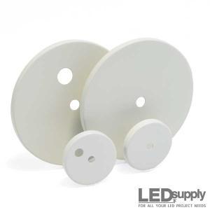
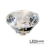
Fitting optics to your LEDs is actually pretty simple, especially if you are familiar with LED supply. We carry a wide range of TIR optics from Carclo that work well with our Cree and Luxeon LED offerings. In our optics section just pick the LED you wish to use and a list of optics and optic holders will come up that are compatible with what you want to use.
Triple optics will work well with our LED stars as they have legs that come down that will fit right into the holes on our star boards. With one-up TIR optics you will need a lens holder, this is where it is important for you to go to the optics page and see what holders fit with what LEDs.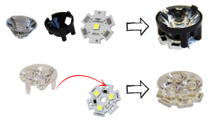
If you are looking to build your own light it is best to test out a few different options and see which provides the light you need. Stay tuned for our next segment on LED optics where we will test LEDs and optics together to see what beams they give off at different distances.