


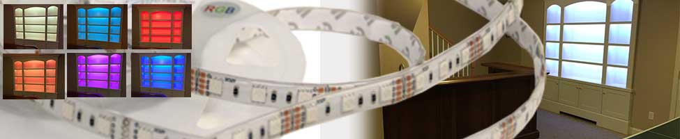
RGB LED Strip Project
RGB LED Strips
Skill Level:
Intermediate
Estimated Time:
2-Hours to 2-Days
Cost:
From $50-$500
Tools
Scissors
Screw Driver
Wire Strippers
Solder Iron Optional
Exacto Knife
Materials
LED Flex Strips:
RGB LED StripsPower Supply:
12VDC 100WDimming/Controller:
3-Channel Dimmer & ControllerHeat Shrink:
Optional Heat ShrinkWire Nuts, Butt Splice Connectors, Electrical Tape
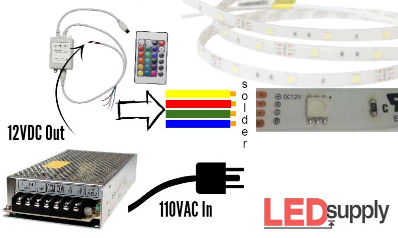
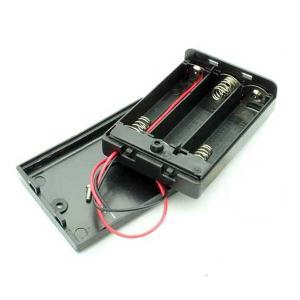
Overview: Power from 110VAC can be taken a couple different ways. Often the easiest method is to use a switching power-supply that can plug directly into a standard outlet. For example, our 12VDC desktop or wall-wart switching power-supplies plug into an outlet and the output cord has a barrel plug connection that can be combined with out screw-in terminal plugs to make clean solderless connections (pictured to the right). The alternative method is hard wiring 110V line voltage with a switching power supply. For this tutorial we will be using the hard wire method with a MeanWell open frame 12VDC output power-supply capable of 100-watts. With the line voltage connected directly to the MeanWell power-supply, the output power is converted to 12VDC and is able to connect directly to a dimmer/controller and then directly to the LED strips. Connections can be made via butt-splice connectors, wire nut connectors or wire nuts. The basic set-up is shown above, convert 110V to 12VDC with the open frame power-supply and then connect the power to the controller and strips.
Pretty simple, but we will go over each step in more detail.
What you should know before starting: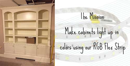
So this is a tutorial that we actually worked out for our customer that he completed, as you can see from the pictures throughout. He wanted RGB Flex Strips in the cabinets in his home and we wanted to share with all our loyal customers so that you can do a similar project with ease if you so wish.
- LED Flexible Strip Wattage: 7.2 Watts/Meter
- LED Flexible Strip Voltage: 12Vdc
- Wattage is equal to = Volts X Amps
- RGB Controller: Line-of-Sight IR Remote, 12V 6A Input MAX, 15 Color Combos & 4 different Lighting Effects
Step 1
 The Power: The first step is to measure out your project and determine the length of LED strip you will need. Knowing the length of the strip gives the required information to determine what size power-supply will be needed. We know from above that each meter of the strip consumes 7.2 watts. So, say we have a full reel (5 meters ~ 15 feet), than the power consumption will be 36 watts. We also know that the voltage of the power supply must be 12VDC, so using the two values we know in the above equation for wattage, we can find amps.
36 Watts = 12VDC x Amps
so...
Amps = 36/12 = 3 Amps
So for this little example we would need at least a 12VDC 3.0 Amp power supply which we actually have here. It is usually a good idea to get a little extra power so it might be a good idea to get the next size up if this were your application.
For this actual project our customer needed 39 feet of the RGB flex strip (roughly 13 meters). This brings up an important point on the forward voltage drop through the LED strips. There is a forward voltage drop through the strips that makes it so 12VDC is only enough to run a length of 30 feet (2 reels) in series. If the total length of strips in your application exceeds 30 feet (which it usually does), then you have to power the remaining length directly from the power source. For example you would have to run wire back from the extra strip all the way back to the power supply.
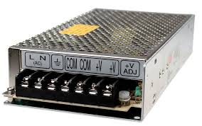
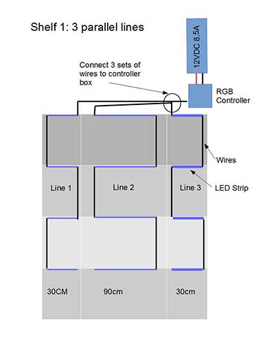 Using the same formulas from above we can see that this project would consume 93.6 Watts. A power supply running all of these would need to be at least 12VDC 7.8 Amp. So for this we could use the MeanWell 12VDC 8.5A (100 Watt) power supply like we said before. This power supply is capable of running a little over 100 watts so it would be able to run this whole application as long as the 9 extra feet was wired back to the supply. However, because of space and not wanting to use too much wire in wiring all the way back to the same power supply, we used two of these power supplies for this job. You can see from the below diagrams that we decided to run 3 parallel lines off of one power supply. That means we ran three separate lines back to the original power source, we could have ran more off of one power supply or ran it all in series but this made the most sense for this application. Then the second power supply ran one line in series for another separate set of shelves.
You can see the picture of the power supply we used above and see how it is easy to hook up with the screw in terminals.
Step 2:
Dimmers and Controllers Step 2 involves setting up your dimming and controllers. With RGB flex strips it will always be important to have a controller as you want to be able to get all you can out of the strips. This will allow you to change the colors, dim, and set the strips to alternate between colors if you want.
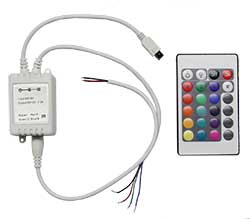 For RGB strips we have the RGB controller (Part#: DIMMER-3CH) shown here with a controller box that connects between the power supply and strips. This controller box connects between your power supply and strips as said before. The input wires from the controller box will connect directly into the screw in terminals on our power supply. Then the output wires from the controller box will connect to the strip(s) you wish to power and control.
The remote is how you control the light. The controller is capable of switching between 15 different color options and it can dim or brighten your LEDs, and has 4 modes for alternating light: Flash, Strobe, Fade and Smooth.
Step 3:
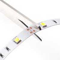 Cutting your LED Strips So now that we have all the supplies we need we can get to setting up our application. You should have mapped out by now the lengths of strips you need and how many, so start cutting your strips if you haven't already done so. These RGB LED Flex Strips we offer can be purchased in 3-15ft. pieces but if you have an in between length then you will have to cut them yourselves. The Strips are easily cut every 3 LEDs or approximately every 4-inches and can be cut with household scissors. You can see from our picture where to cut, right along the black line in between the solder points.
After measuring and cutting the LED strips, it is time to add wire to the end of strips where power will be passed from one strip to another. So first measure out the length of wire leads you will need in order to get to the power source or the next strip. For RGB strips you will need 4 wires, 1 is neutral (yellow) and the rest control the 3 LED colors: Red, Green and Blue. We usually will use red, green and blue wires for these (we keep it simple).
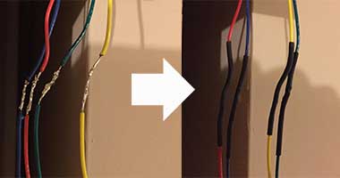
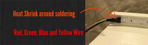 The strips are sealed in silicone, so you will need a razor blade to slice back the silicone for access to the 4 gold solder pads. Our method of adding wires is to carefully cut the silicone close to the solder pad surface without disconnecting the silicone completely. Then solder your wires to the solder points: yellow wire to the (+) point, Red wire to the R point, Green wire to the G point, and Blue wire to the B point. Then use heat-shrink material to cover the connections. Heat shrink is not completely necessary but it is a good thing to do especially if these connections could be exposed to any moisture.
These wires can be connected from the solder point of one strip to the solder points of the other or you can use end-to-end connectors, butt-splice connectors, or wire-nut connectors.
Step 4:

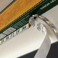
Mount/Adhere Strips Now that we have all of our strips soldered with wires we can adhere them to a surface. The strips come with a strong 3M double-sided adhesive for easy mounting. Clean your surface and dry first to make the best bond. Then peel the 3M backing off the strip as you can see in the picture and carefully stick strip flat on your surface and press down to make sure it sticks well.
The below picture shows how the strips for this project were mounted, right under the lip of the cabinet shelving.
Step 5:
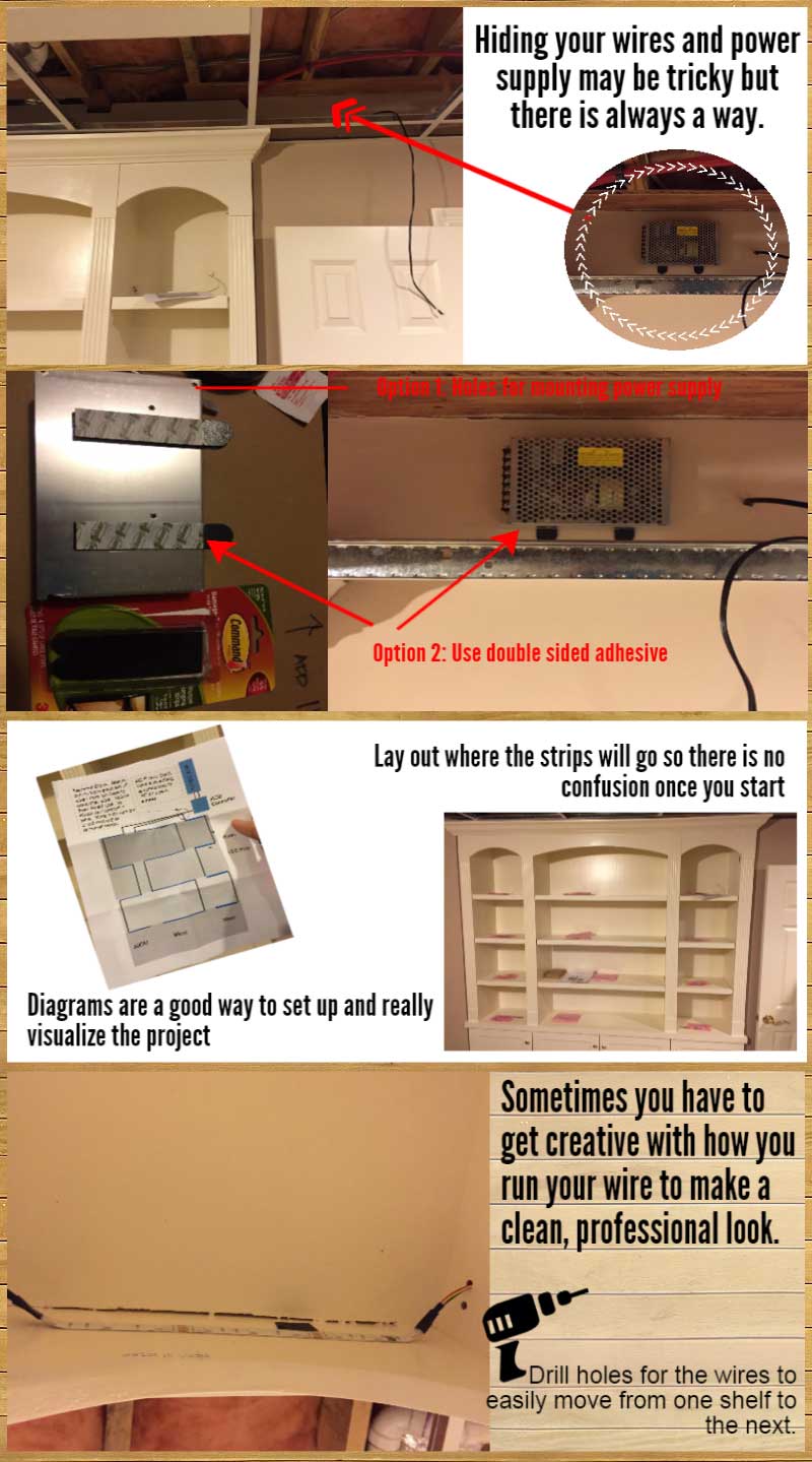
Finishing off connections Now that we have all our strips mounted in the correct positions we can finish all our connections for the final step in setting the system up. We will wire the system backwards (starting with strips and ending with wiring the power supply) as the strips are the hardest part as you may need to run extra wire in between your lengths and make sure you have it all set. This is when you will go back to your original set up drawing and see where your lines will run, how many lines you have and what power supply they will run to (if you have more than one). Once you know this it is time to start wiring the strips.
Wiring the strips together is pretty simple, for this project we just soldered the wires from the strips together and used electrical tape to solidify the connections and protect them as you can see from the below pictures. Another option would be to use our RGB connectors on the ends of wire and then connecting it right to the next strip.
Ok, strips are connected, now it's time to connect them to the controller and power supply. First connect your wires from your first strips to the controller box or boxes they need to go to. Just match the colored wires from your strips to the controller box output wires. The yellow wire from your strip will connect to the black wire on the controller.
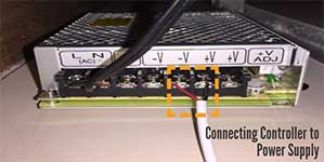 Once this is done you can connect your controllers to the MeanWell 100 Watt power supply. Connect the red wire to one of the V- terminals and the black wire to one of the V+ terminals as shown in the picture below. To connect all you need is a screwdriver to open the terminal connection and then clamp it down once you have the wires in place.
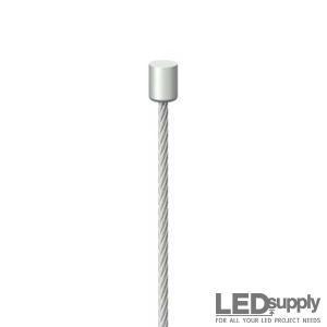
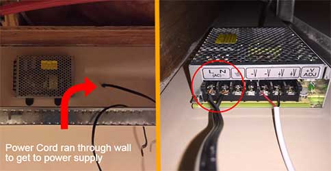
Now the last connections we need to make is connecting our power to the power supply. This is hardwired so we are using our 72-inch power cord to connect the power. This power cord will need to be wired into the control box and then plugged into an outlet nearby. You can see from the picture how he ran the cord over to the power supply and then in the next image how it connects in. The wire with writing on it is connected to 'N' on the power supply and the one without writing will go into the 'L' as shown.
Step 6:
Testing We should be all set for this application but it is always a good idea to go back through and make sure all your connections are secure and hooked to the right parts. Once you make sure all connections are secure and correct then test out your strips. Turn them all and work with alternating the colors to make sure all the connections work with each LED. If all the colors work from the remote and all then you've successfully completed the project. Looks like our customer was right on the money as you can see the lights working and the short video of them alternating through the colors.
Below I've added some pictures from this project with short descriptions of what was done. These are helpful tips in setting the project up that may not be necessary for every project, but give some good ideas for mounting the project and setting up clean, professional looking lighting.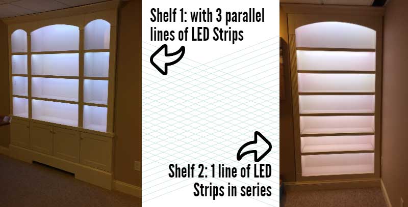


- Low Prices
- Knowledgeable Support
- 100K+ Orders Shipped
- Free Shipping
- Bulk Discounts
- 2,000+ 5-Star Reviews
LEDSupply is a trusted provider of engineered LED lighting solutions, serving OEMs, integrators, contractors, and lighting professionals with technical expertise, application support, and carefully curated high-performance products. Backed by decades of industry experience, our team helps customers move from components to complete lighting solutions with confidence. Learn More


Shipping
LEDSupply does NOT profit from the shipping or handling of your order!
Orders received before 3PM EST will be safely packaged and quickly shipped the same business day. If your order is NOT shipped the same business day, LEDSupply will offer a 5% discount off your next order.
All orders SHIP FROM:
296 Beanville Road
Randolph, Vermont 05060
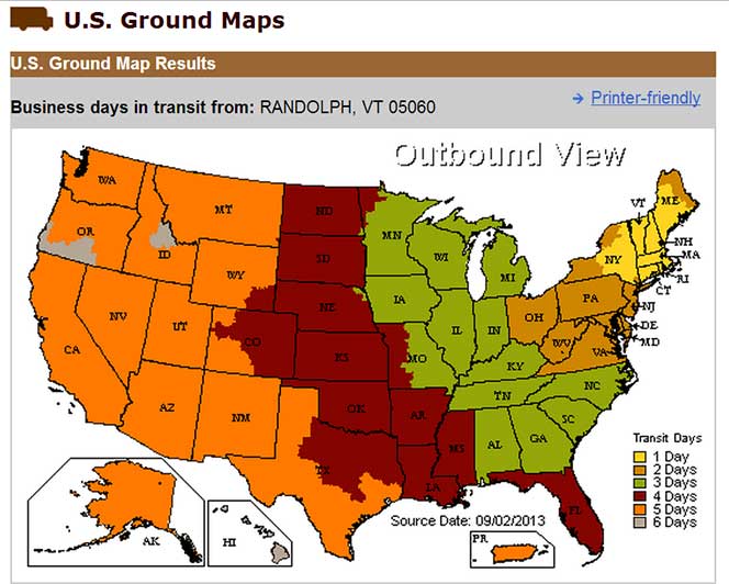
See respective ZONE maps below for SPECIFIC delivery time to your location:
Any order that does not qualify for free shipping, will by default include a discount of equal value to the free shipping offer.
The shipping offered is meant to provide the widest variety of shipping options at the lowest price:
- FREE USPS First Class SHIPPING on orders under 13oz & >$49.99
- $5.99 USPS First Class on orders under 13oz & <$49.99
- $15.99 2-Day SHIPPING on orders under 2lbs
- $11.99 GROUND SHIPPING on orders under 2lbs
- $39.99 Standard Overnight SHIPPING on orders under 2lbs
- $49.99 Priority Overnight SHIPPING on orders under 2lbs
- Real-Time Rates are calculated for all International shipments
- *Base Rate + $1.99/lb for orders over 2lbs
USPS Priority Delivery Zone Map: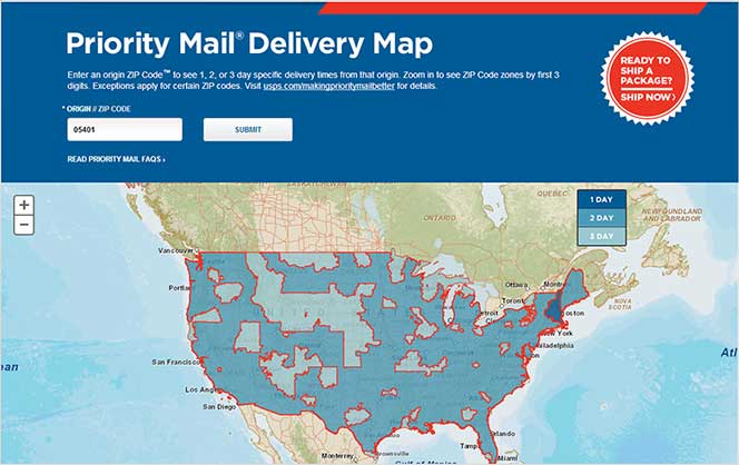
FedEX Ground Delivery Zone Map: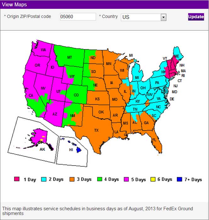
UPS Ground Delivery Zone Map: