


FlexBlock LED Driver
The extremely compact dual-mode FlexBlock is a true current regulated LED driver for powering high-power or high-brightness (HB) LEDs or LED arrays; because the forward voltage of LEDs can change based on several environmental factors as well as the age of the LED, it is important to use this type of driver in an LED system to help avoid thermal runaway. The FlexBlock includes a fast response current-sensing circuit for applications where flashing or strobe of LEDs is required and its dimming input is also compatible with 0-10V wall mount dimmers like the A019 low voltage dimming control.
BUT…Here is what sets the FlexBlock apart from other constant current LED drivers.
The A011 FlexBlock is capable of two different modes:
Buck-Boost Mode
The versatility engineered into the FlexBlock allows it to handle LED loads that are ABOVE, BELOW or the SAME voltage as the power supply. This standard mode, called Buck-Boost mode, is recommend for loads up to 6 LEDs, but has the ability to output: 48Vdc minus the input Voltage. For example, if your input voltage is 12Vdc, the FlexBlock technically has the capability to output 36Vdc; at the same time and in the same mode, the FlexBlock could also run only 1-4 LEDs from 12Vdc.
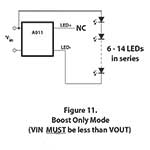
Figure 11 – Boost-Only
The FlexBlocks most efficient mode is Boost-Only. In this mode the FlexBlock LED+ output is not used, and the positive end of the LED load is instead connected to Vin+ (shown in figure 11). In Boost-Only mode the output voltage can reach 48Vdc, but it is extremely important that the Vin be less than the Vout.
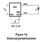
Figure 14 – Potentiometer
Dimming with potentiometer: The simplest method for dimming the FlexBlock is with a 20K Ohm potentiometer. This gives a 0%, 5-100% range of dimming. Figure 14 shows an example connection. Multiple FlexBlock can be dimmed together, however the value of the potentiometer should approximately be (20K Ohm / # of FlexBlocks).
Dimming with 0-10V wall dimmer: The preferred choice of dimming a FlexBlock is with the A019 Low Voltage Dimming Control module or another commercial wall dimming 0-10V control; the A019 can easily handle several drivers. The 0-10V control can also be supplied by a commercial lighting controller that has current sinking 0-10V outputs.
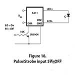
Figure 18 – PWM
On/Off Control
The potentiometer in Figure 14 may be replaced by apush-button or toggle switch for on/off control. The output current will be zero and the input current will drop to the quiescent level when the switch is closed. Figures 16 and 17 show external dimming control combined with on/off control.
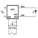
Figure 16
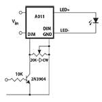
Figure 17
Thermal Management
The FlexBlock can run many LED load configurations with no heat sinking in an ambient of 25°C. In applications with elevated ambient temperatures, such as those that might be experienced inside an enclosed fixture, additional heat sinking may be required. If the temperature of the FlexBlock (measured at the T marking on the label) exceeds 60°C, additional heat sinking is recommended. If the temperature of the FlexBlock exceeds 80°C, additional heat sinking is required. The best surface for removing heat form the FlexBlock is the back side (opposite the label). If the FlexBlock becomes too hot during use, it will reduce the output current to limit the power dissipation. If the temperature continues to rise, the driver will turn off until the temperature drops to a safe level.
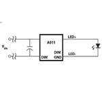
Figure 20
The LEDs being driven should be located as close to the FlexBlock LED output as possible. 18AWG wire should be adequate for most wiring, but a heavier gauge should be considered when long leads are necessary. The power input wires should also be kept short. Where the power source is located several feet from the unit, a 100μF or larger, 50V capacitor may be required across the input terminals as shown in Figure 20.
FlexBlock Features:
DC input voltage up to 32V
350mA or 700mA constant current output
Extremely small form factor (2.0”x1.2”x0.38”)
18 AWG wires for easy electrical connections
External analog/digital intensity control
External potentiometer intensity control (0%, 5-100%)
Continuous output short circuit protection
Continuous output open circuit protection
Input reverse polarity protection with Polarifet™ Technology
Pulse and strobe capable (dim input)
FlexBlock Applications:
Solar & Landscape Lighting
Architectural Lighting
Track Lighting
Automotive & Marine Lighting
Portable Lighting & Flashlights
Point of Purchase Lighting
Desk & Reading Lamps
Signal & marker Lighting
Flashing & Strobe Lighting
Cabinet & Display Case Lighting
Sign & Channel Letters


The Buck-Boosting FlexBlock LED Driver is interesting. How much for a few to test?
Hi Jim, we sell the FlexBlock with no minimum orders and free shipping. The cost per unit for under 10pcs is $17.99ea. Here is a link: http://www.ledsupply.com/flexblock-constant-current-led-drivers
I have a question… in the A011 data sheet, figure 10, it shows two strings of LEDs which are placed in parallel.
How is ballasting controlled such that one side of the LEDs doesn’t get a lot more current? As I understand it, even LEDs from the same die lot can have different forward voltages, which would cause one leg or the other to hog the current.
How does that work?
Thanks!
Hi Frank, Great question! As long as each string(s) are equal in length and have a minimum of three LEDs in each string, any difference in forward voltages between the LEDs and or between the two different strings will not be great enough to cause current hogging on either string(s). The data-sheet addresses this issue by saying the following: “Parallel strings of LEDs can be driven directly with no additional circuitry required to insure current sharing. The nature of the LEDs themselves will provide sufficient current sharing if the parallel strings comprise three or more junctions each, and are identical in length.”
Hi, I have a question about the
FlexBlock Buck-Boost DC LED Driver
I have 8 LED chips, each one requires 24 to 30 volts at 200ma that I need to run with a 12v power supply (on a motorcycle).
Can 1 flexblock buck-boost driver run them all?
if so;
-do I run them in parallel or in series?
-or do I have to wire groups of 2 in series and then wire those groups in parallel?
-what rating flexblock buck-boost driver should I buy?
-would it be necessary to buy the dimmer, or set the current with a resistor to match 200ma? or is it alright if there is more current fed to the LED chip if I were to buy the 700ma (A011-D-V-700)?
HELP!
Thanks!
Hey Alan,
Great questions and it looks like you have all the specs you need to know. The FlexBlock in Buck-Boost mode can carry up to 36 volts (48V – 12VDC input). This makes it so you can only run one in series from this as they fluctuate from 24-30 and two in series would obviously be greater than the 36V limit. This being said, however, you could run 4 of them in parallel off of a FlexBlock as that would only divide the current. I would use a 700mA FlexBlock as then your LEDs would be running at 175mA (700/4) which is close to the 200mA you mentioned.
So with this set up you would want 2 700mA FlexBlock each running 4 in parallel. You would not need a dimmer or resistor as like I said, when circuits are in parallel they divide the drive current by how many strings there are, in this case 4. Let me know if there is an issue in running the LEDs 25mA below 200 or if you need help setting up a parallel circuit.
[…] So when using a 12VDC power supply and the XPG2 LEDs from above how many could we run with the 700mA FlexBlock? Your max output voltage is 36VDC (48-12) and the forward voltage of the XPG2 running at 700mA is 2.9 so by dividing 36VDC by this we see that this driver could power 12 LEDs. In Boost-Only Mode the FlexBlock can output up to 48VDC from as little as 10VDC. So if you were in Boost-Only mode you could power up to 16 LEDs (48/2.9). Here we go over using a FlexBlock boosting driver to power your LEDs in depth. […]