


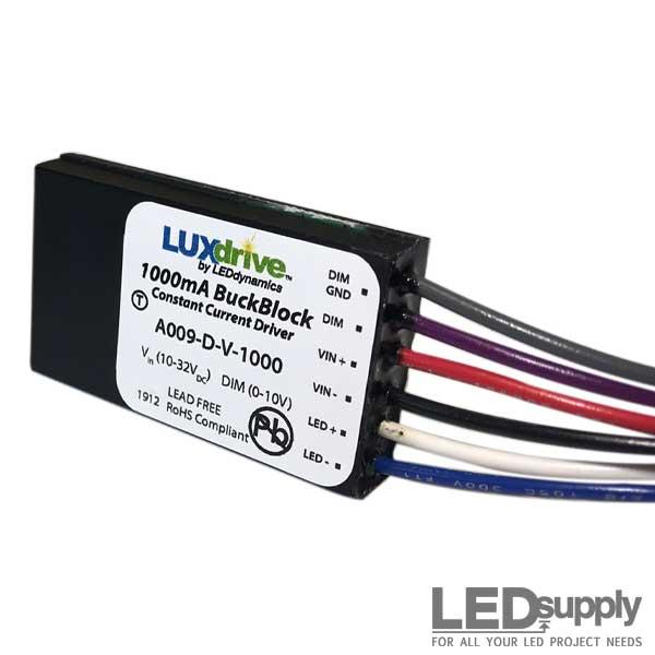
BuckBlock DC LED Driver


More images

Purchase
SAME DAY SHIPPING
- Low-Voltage DC Constant Current Device
- MADE IN USA
- 0-10V and Resistance Dimming


Product Details
| Output Current: 2100mA, 1400mA & 1000mA | Input Voltage Range: 10Vdc-32Vdc |
| Dimming: 0-10V | Output Protection: Short & Open Circuit |
| Input Protection: Reverse Polarity with Polarifet Technology | Size: 2.0"(L) X 1.2"(W) X 0.38"(H) |
| External Control: Analog/Digital Intensity Control | Potentiometer Control: 0-100% Intensity |
| Efficiency: 90% | Connection: 18 AWG Wires |
Description
The LuxDrive™ A009 series BuckBlock™ LED power modules are high output wide range constant current LED drivers for powering high-brightness (HB) LEDs at constant high-output currents. Where standard power supplies deliver a fixed voltage to the output, the BuckBlock is engineered to produce a fixed current. The output voltage will adjust as required to maintain the specified output current with differing forward voltage drops of LEDs. The BuckBlock features a fast response current-sensing circuit enabling the device to flash or strobe LEDs and the output from the BuckBlock includes external dimming using common 0-10V low voltage dimmers. The form factor of the BuckBlock is extremely low profile, fully potted and comes with six inch 18AWG colored leads, making installation into tight spaces fast and easy.
Technical Documentation
Product Selection
| Part Number |
DC Input (VDC) | Output | Control Dimming (V) |
Connection Type |
||||
|---|---|---|---|---|---|---|---|---|
| Min. | Max. | Current mA |
Tolerance (±) |
Efficiency (%) |
Max Voltage | |||
| A009-D-V-1000 | 10 | 32 | 1000 | 10% | 90 | 80% of Vin | 0-10 | (6) 18AWG 6" Wires |
| A009-D-V-1400 | 10 | 32 | 1400 | 10% | 90 | 75% of Vin | 0-10 | (6) 18AWG 6" Wires |
| A009-D-V-2100 | 10 | 32 | 2100 | 10% | 90 | 50% of Vin | 0-10 | (6) 18AWG 6" Wires |
Absolute Maximum Ratings
| Parameter | Maximum Performance |
|---|---|
| Dimming Input, turn on threshold | 1.7V ±5% |
| Dimming Input, full on threshold | 9V ±5% |
| External pot adjustment range | 0%, 5-100% |
| Output rise time | <1.5ms |
| Output fall time | <100 s="" td=""> |
| Quiescent current (DIM = 0V) | <4.5 ma="" td=""> |
| Storage Temperature | -40°C - 125°C |
| Operating Temperature | -40°C - 80°C |
Important Information
Application Information: The BuckBlockTM High Output LED Power Module is a high-efficiency dc to dc converter that delivers a fixed output current by varying the output voltage as required to maintain the specified current. Because the forward voltage of LEDs can change based on several environmental factors as well as the age of the LED, it is important to use this type of driver in an LED system. The higher output currents are ideal for driving multiple strings of LEDs or high-power LED modules. A fast response current-sensing circuit permits the unit to be used in applications where flashing or pulsing of the LEDs is required. Several options are available allowing for use with many types of LEDs and in a variety of operating modes.
Fixed Current Drive: When the dimming wires (purple/gray) are left unconnected, the A009 is designed to supply its rated current to one or more LED junctions. For example, a 2100mA rated unit will drive up to four white 2100mA LEDs connected in series at 24VDC. Due to the nature of the buck regulator, the input voltage must always be higher than the total forward voltage drop of the LED junction(s) connected in series. Thus, for a series string of four junctions having an average forward drop of 3.15V each, the required minimum input voltage will be 24VDC. A standard 24VDC power supply is a good choice for this application. Refer to page three for the max Vout/Vin ratings for the various drive currents.
Figures 10 and 11 show a 1400mA and 2100mA unit driving multiple LEDs. Note that parallel strings of LEDs can be driven directly with no additional circuitry required to insure current sharing. The nature of the LEDs themselves will provide sufficient current sharing if the parallel strings comprise three or more junctions each, and are identical in length.
Adjustable Current - External Control - "V" Model: Figures 14 and 15 show the ease of dimming the A009 BuckBlockTM High Output LED Power Module. Figure 14 shows the simplest dimming configuration using a 20K Ohm potentiometer. This gives a 0-100% range of dimming. If multiple A009 modules are to be dimmed with a single potentiometer, the value of the potentiometer should be approximately (20KΩ/N) where N is the number of modules.
Figure 15 shows a 0-10V wall dimmer, such as LEDdynamics A019 Low Voltage Dimming Control, being used to control the LED brightness. This is the preferred choice for dimming multiple units, as the 0-10V dimmer can handle several drivers. The 0-10V input can also be supplied by a commercial lighting controller that has current-sinking 0-10V outputs, allowing the integration of LEDs with other forms of lighting in large automated systems.
For large systems where several distant BuckBlock modules will be dimmed together, it is important to use a heavier gauge wire (such as 18AWG) to run the DIM lines in a star wiring pattern (where each module has a run all the way back to the dimmer). This will help to negate any voltage drops along the DIM wires that could cause some lamps to dim differently than others.
For more advanced control, the 0-10V input can be Pulse Width Modulated (PWM). Figure 18 shows how interfacing with a micro-controller can easily be accomplished with a 2N3904 or equivalent transistor. A PWM frequency of 200Hz is recommended. This configuration can also be used to strobe or pulse the LEDs with a TTL or CMOS logic signal.
In addition to the configurations described above, the BuckBlock may also be driven by a D to A converter. The D/A converter must be able to sink at least 1ma of current from the 0-10V input of the BuckBlock. If the D/A converter cannot sink current, a voltage follower with an open collector output should be used between the D/A converter and the 0-10V input.
If the dimming control circuit used with the BuckBlock has the potential to exceed 10V, current into the DIM input needs to be limited to 10mA or less. See figure 8.
External On/Off Control: Where a manual on/off control is desired, the potentiometer in Figure 14 may be replaced by a push-button or toggle switch. The output current will be zero and the input current will drop to the quiescent level when the switch is closed. Figures 16 and 17 show external dimming control combined with on/off control.
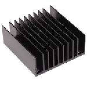
Thermal Management: The BuckBlock can run many LED load configurations with no additional heat sinking in an ambient of 25°C. In situations with elevated ambient temperatures, such as those that might be experience inside an enclosed fixture, additional heat sinking may be required. If the temperature of the driver (as measured at the T marking on the label) exceeds 60°C, additional heat sinking is recommended. If the temperature of the driver exceeds 80°C, additional heat sinking is required.
The best surface for removing heat form the BuckBlock is the back side (opposite the labeled side). The module can be attached to a heat sink with thermal grease and a mounting bracket that presses the unit firmly against the heat sink, or with double-sided tape that provides both the thermal path and mechanical mounting. When using tape (such as 3M F9469PC, a Very High Bond (VHB) tape suitable for permanent mounting), using a thinner variety (0.005" thick or less) will aid in getting the heat through the tape and to the heat sink. Care should be taken when positioning the BuckBlock module with VHB tape as the high bond strength makes removing or re-positioning the module very difficult.
If the BuckBlock becomes too hot during use, it will reduce the output current to limit the power dissipation. If the temperature continues to rise, the driver will turn off until the temperature drops to a safe level.
Connections: In all cases, the LEDs being driven should be located as close to the A009 LED output as possible. 18AWG wire should be adequate for most wiring, but a heavier gauge should be considered when the long leads are required
The power input wires should also be kept short. Where the power source is located several feet from the unit, a 100μF or larger, 50V capacitor may be required across the input terminals as shown in Figure 20.
Note: The above are product highlights and not the complete manufacturers datasheet. Please view the .pdf for complete specifications.
Full Documentation
Accessories
General Accessories

AWG Stranded Wire

Wire Nuts – 24AWG to 14AWG Spring Core Insulated Connectors

Lever In-Line Connector - 1 to 5 Conductor Models

Butt Splice Quick Wire Connectors

HexaTherm Tape - Thermally Conductive Double-Side Tape
BuckBlock Accessories
AWG Stranded Wire

Potentiometer - 20K Ohm

0-10V Wall Mount Dimming Control
Shipping
LEDSupply does NOT profit from the shipping or handling of your order!
Orders received before 3PM EST will be safely packaged and quickly shipped the same business day. If your order is NOT shipped the same business day, LEDSupply will offer a 5% discount off your next order.
All orders SHIP FROM:
296 Beanville Road
Randolph, Vermont 05060
See respective ZONE maps below for SPECIFIC delivery time to your location:
Any order that does not qualify for free shipping, will by default include a discount of equal value to the free shipping offer.
The shipping offered is meant to provide the widest variety of shipping options at the lowest price:
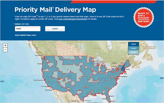
USPS Priority Delivery Zone Map:
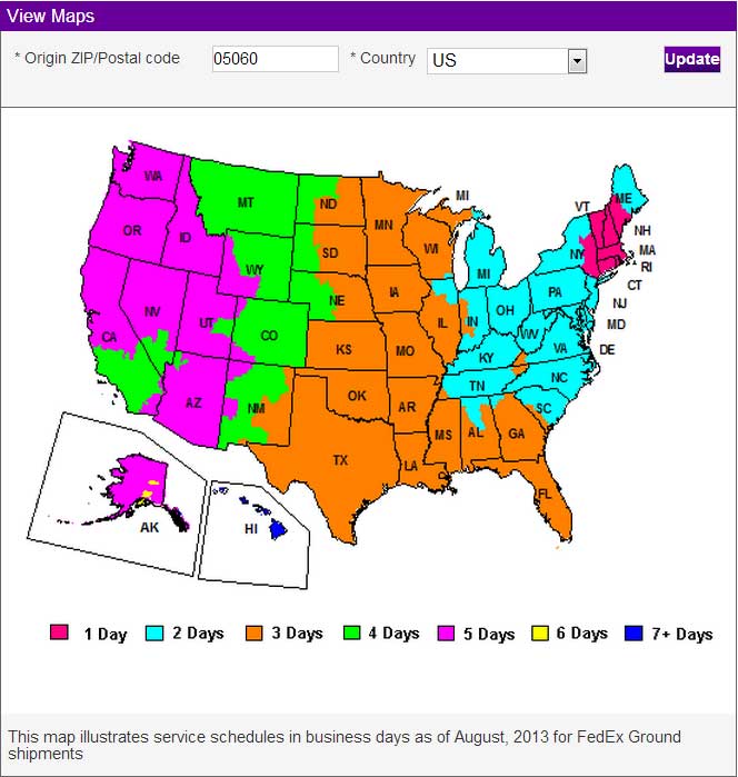
FedEX Ground Delivery Zone Map:
UPS Ground Delivery Zone Map:


- Low Prices
- Knowledgeable Support
- 100K+ Orders Shipped
- Free Shipping
- Bulk Discounts
- 2,000+ 5-Star Reviews
LEDSupply is a trusted provider of engineered LED lighting solutions, serving OEMs, integrators, contractors, and lighting professionals with technical expertise, application support, and carefully curated high-performance products. Backed by decades of industry experience, our team helps customers move from components to complete lighting solutions with confidence. Learn More


Shipping
LEDSupply does NOT profit from the shipping or handling of your order!
Orders received before 3PM EST will be safely packaged and quickly shipped the same business day. If your order is NOT shipped the same business day, LEDSupply will offer a 5% discount off your next order.
All orders SHIP FROM:
296 Beanville Road
Randolph, Vermont 05060
See respective ZONE maps below for SPECIFIC delivery time to your location:
Any order that does not qualify for free shipping, will by default include a discount of equal value to the free shipping offer.
The shipping offered is meant to provide the widest variety of shipping options at the lowest price:
- FREE USPS First Class SHIPPING on orders under 13oz & >$49.99
- $5.99 USPS First Class on orders under 13oz & <$49.99
- $15.99 2-Day SHIPPING on orders under 2lbs
- $11.99 GROUND SHIPPING on orders under 2lbs
- $39.99 Standard Overnight SHIPPING on orders under 2lbs
- $49.99 Priority Overnight SHIPPING on orders under 2lbs
- Real-Time Rates are calculated for all International shipments
- *Base Rate + $1.99/lb for orders over 2lbs
USPS Priority Delivery Zone Map:
FedEX Ground Delivery Zone Map:
UPS Ground Delivery Zone Map: