


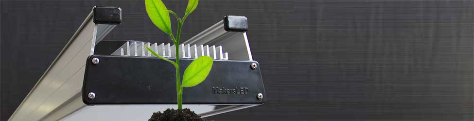
MakersLED LED Grow Light
DIY MakersLED Grow Light Project
Skill Level:
INTERMEDIATE
Estimated Time:
1 Weekend
Cost:
Under $1000
Tools
Solder Iron & Solder
Wire Strippers
Tweezers
Hand-held Drill
Latex Gloves
Philips Screwdriver
10mm Wrench
Red, Black & Blue Sharpie Markers
Materials
3-Feet:
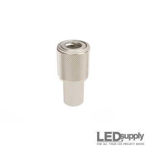
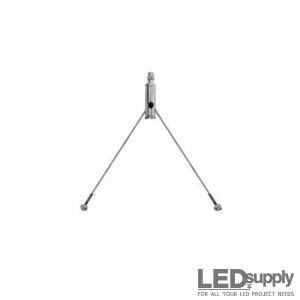
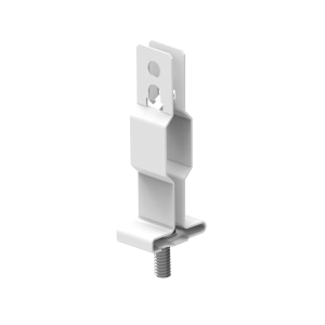
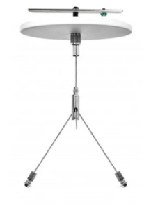
MakersLED & Hanging Kit - #MAKERSLED36pcs:
Deep-Red Luxeon LED - #07040-PDRED-C9pcs:
Red Luxeon LED - #07040-PD000-F9pcs:
Red-Orange Luxeon LED - #07040-PH000-G18pcs:
Royal-Blue Luxeon LED - #07040-PR000-B18pcs:
Warm-White Cree LED - #CREEXML-WW2206pcs:
700mA FlexBlock - #0A011-D-V-7003pcs:
1000mA BuckBlock - #0A009-D-V-10003pcs:
1400mA BuckBlock - #0A009-D-V-14003pcs:
24VDC Power Supply - #24VDC45A3pcs:
Arctic Silver Epoxy - #ASTA-7GVarying:
24 Gauge Stranded Wire - #24AWG-This is a legal prop 215 grow-
What up. Been lurking around the led threads and finally decided to do a grow thread with my new LED. I’ve been on the fence for a while and decided to take the leap after seeing some success with other people's grow. After doing much research, I decided to get some quality parts instead of ordering the ones made in china. The Chinese fixtures are cheaper initially but who knows what is under the hood? Could be a sweet ferrari body with a kia engine lol. Anywho, on with the show. I decided to go with a shorter strain and chose the Alien Blackberry for that purpose. It finishes anywhere between 2.5-4’. Soil will be the grow medium. I’m curious how much yield will result from this light.
I claim that this saves money. Why is that? To begin with, LEDs last for 50,000 hours. After that, they drop about 30% in brightness. How many times would you need to replace halide bulbs in 50,000 hours of burn time? Also, power consumption is far less.
Step 1
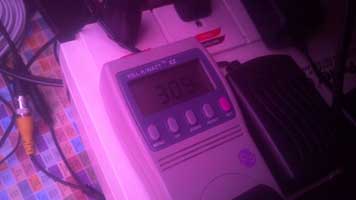
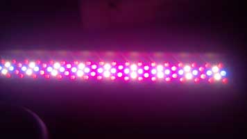 Here is the LED fixture. I forgot to put on some shades when I turned it on; super bright. It fluctuates between 309w and 311w
Step 2
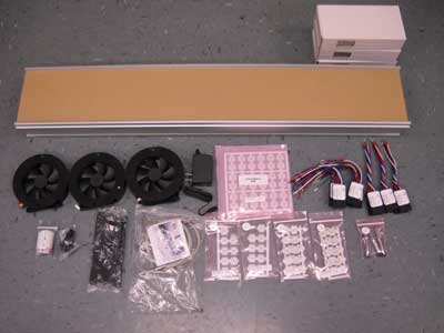
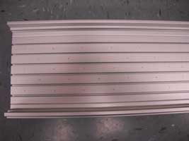
Organize Materials – Double-check all part#'s & quantities
DOT LED location on heatsink w/ appropriate color sharpie markers
1. See LED Schematic
2. Measure, Mark & Divide the heatsink into equal 3rds (DOT 1-foot at a time)
3. Start “Approximately” 1” in from end and space DOTs 2-inches apart)
*IMPORTANT: Apply solder to the solder pads BEFORE attaching the LEDs to the heatsink! If you don't, getting solder to stick to the pads is very difficult.
Step 3
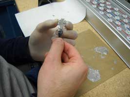
Apply Epoxy & Place LEDs
1. Set-up correct pattern of LEDs before applying epoxy
2. Mix appropriate amount of Epoxy (5-minute cure time) – Shoot for 8-LEDs every 5-minutes
3. Hold LED in left hand between index finger and thumb
4. Apply Epoxy down center, rotate 25-degrees in fingers and Epoxy down center, rotate opposite direction 50-degrees and Epoxy down center
5. Place LED over appropriate DOT on heatsink
6. PUSH down with Right hand
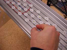
Step 5
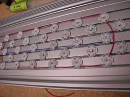
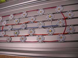
Solder 1st Circuit (1st Foot) – Repeat Steps for 2nd & 3rd Circuit (2nd & 3rd Foot)
1. See LED/WIRING Schematic
2. Wire Royal-Blue LEDs: (Above Left PIC)
3. Wire Deep-Red LEDs: (Above Center PIC)
4. Wire Reds & Red-Orange
5. Wire Warm-White LEDs: (Above Right PIC)
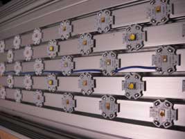
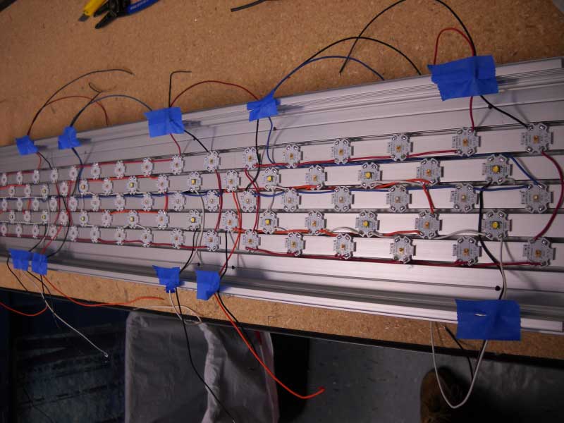
Complete EACH circuit with Positive & Negative Wires (Right PIC)
1. For the Positive Wire use the appropriate COLOR WIRE for the color of the LED (Red Wire for Deep-Red Circuit, Orange Wire for Red & Red-Orange Circuit, White Wire for Warm-White Circuit and Blue Wire for Royal-Blue Circuit)
2. Use Black for ALL Negative connections
3. Cut ALL these wires long enough to run to the side (where drill holes will eventually be) and be run up through the heatsink with enough wire to work with
Step 6
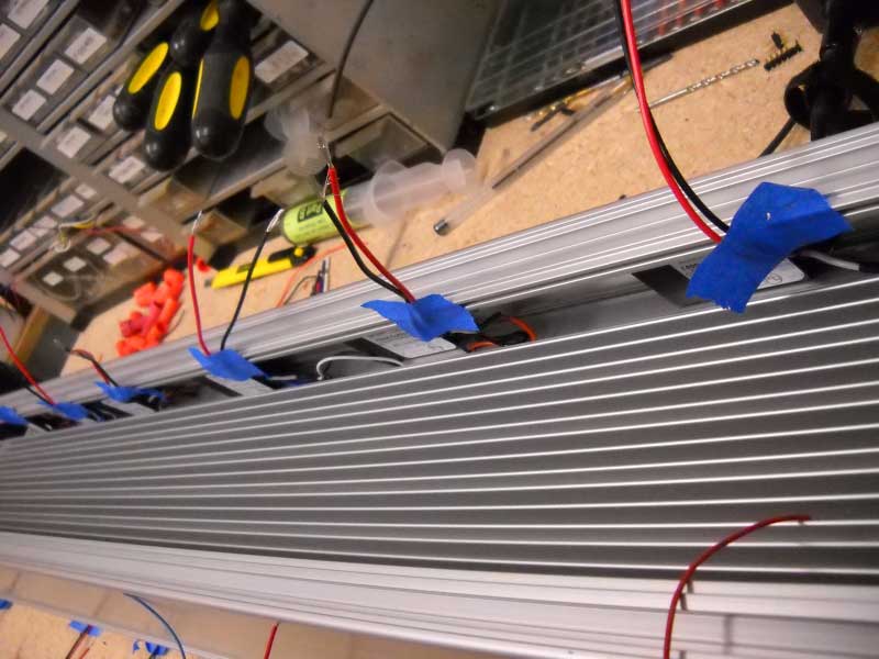
 Drill Holes for Wires:
1. There will be six holes per side
2. Run Positive & Negative wires neatly and in the straightest path to the side of heat-sink and determine where all the holes need to be drilled. Mark & Drill.
3. Run Wires through Drill-Holes & Tape to the side of the heat-sink (PIC left)
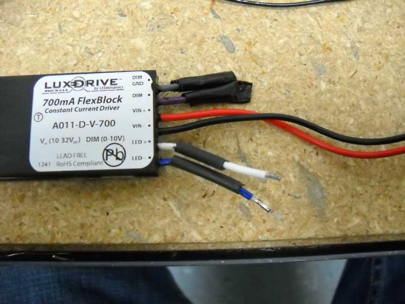
4. Solder Positive & Negative wires to Positive & Negative Output Wires of APPROPRIATE LED Driver: 700mA FlexBock for Deep-Red in Boost-Only Mode (see documentation), 700mA FlexBock for Red & Red-Orange, 1000mA BuckBlock for Royal-Blue and 1400mA BuckBlock for Warm-White.
5. Connections are made by stripping back both wires, adding heat-shrink tubing to wires, Solder wires together and cover connection with heat-shrink. Cut away excess wire before stripping to save space. Cut away dimming wires and tape over end of wire (PIC Left). Special Connection must be made for Deep-Red Circuit (see FlexBock Datasheet for Boost-Only mode connection diagram). Alternatively, wire nuts could be used to make connections (space limitation).
Step 7
Locate ALL Red & Black INPUT wires on the LED Drivers and TAPE them to the side of the heat-sink (PIC Right)
One-Foot at a time: Solder RED wire to RED Wire on LED Drivers, long enough to stretch the length of the heat-sink (PIC Right)
One-Foot at a time: Solder Black wire to Black Wire on LED Drivers, long enough to stretch the length of the heat-sink
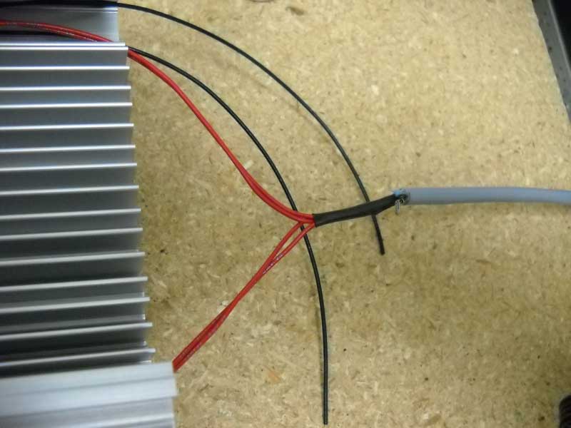
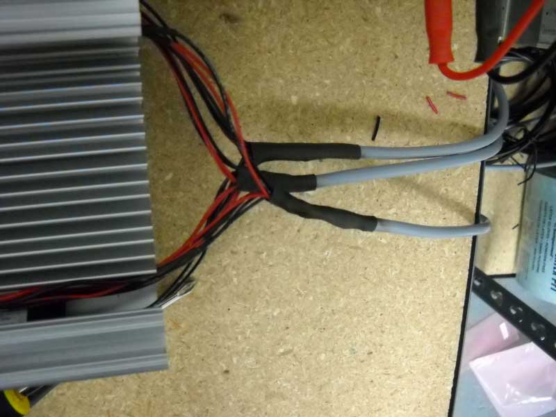
Connect ALL Red wires to each other, Connect ALL Black wires to each other
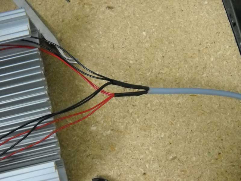
Connect ALL Red wires to the Red wire on the 2 Conductor cable, Connect ALL Black wires to the Black wire on the 2 Conductor Cable
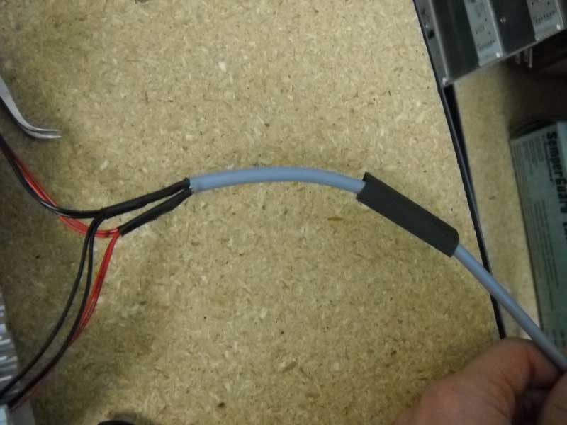
Heat-Shrink Red & Black Connections to the 2 Conductor Cable
Step 8
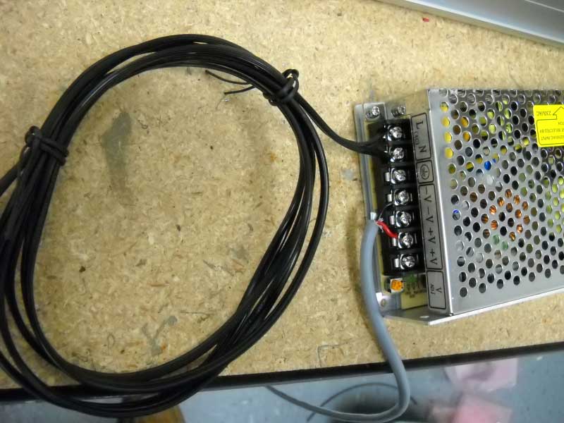
1. Connect 2-conductor Red & Black wires to appropriate Power-Supply Output
2. Connect Power-Supply CORD to Power-Supply, Wire with writing goes to “L”
3. Plug in the Power-Supply to TEST that the 1st Foot Lights-Up! Repeat for the next two-feet
Step 9
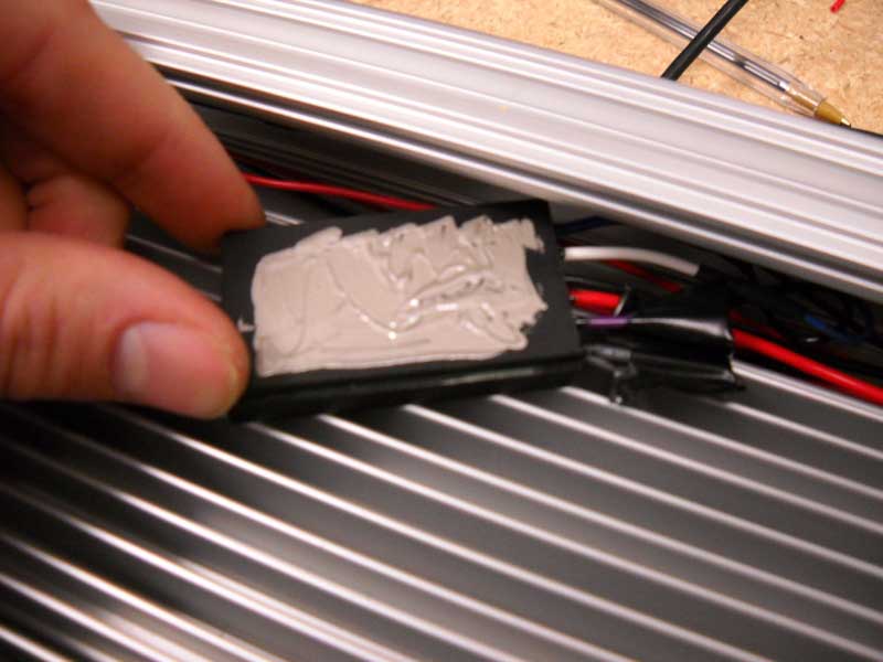
Epoxy Drivers to side of heat-sink, while the Epoxy is drying the drivers may need something to hold them against the heat-sink
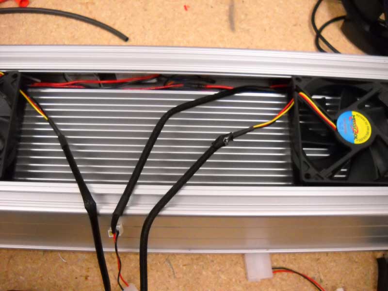
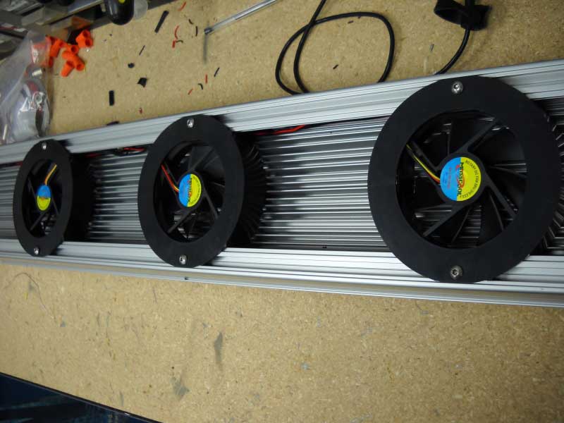
Position fans, writing up
Run Fan wiring to central location (PIC# 30)
Step 10
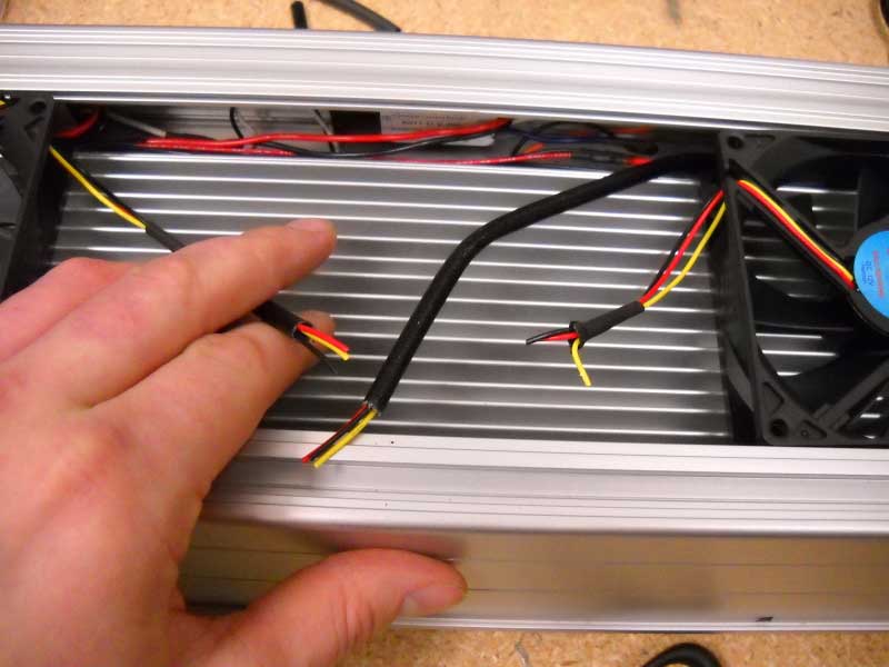
1. Cut excess wire
2. Don't use yellow Attach
3. ALL REDs, Attach ALL Blacks
4. Strip off barrel plug on 12VDC 1.0AMP fan power-supply and expose wires, wire with writing is Positive Attach and heat-shrink RED wires to positive wire on power-supply Attach and heat-shrink BLACK wires to Negative wire on power-supply
5. Hide excess cords and wires along edge of heat-sink and run plug out with the other wires
Final
Attach rubber end plugs (use soap and water), attach end caps, attach Hangers: 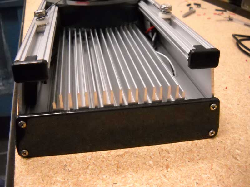


- Low Prices
- Knowledgeable Support
- 100K+ Orders Shipped
- Free Shipping
- Bulk Discounts
- 2,000+ 5-Star Reviews
LEDSupply is built, owned and operated by a select few, all with technical backgrounds and over 50-years combined experience in the LED industry. Click here for more about us.


Shipping
LEDSupply does NOT profit from the shipping or handling of your order!
Orders received before 3PM EST will be safely packaged and quickly shipped the same business day. If your order is NOT shipped the same business day, LEDSupply will offer a 5% discount off your next order.
All orders SHIP FROM:
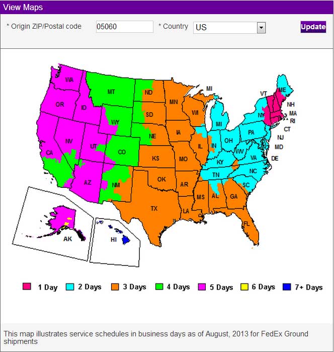
296 Beanville Road
Randolph, Vermont 05060
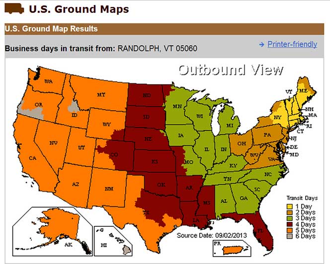
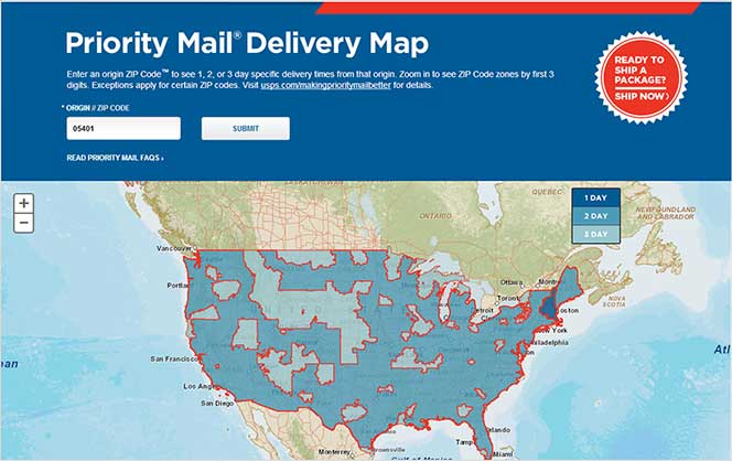
See respective ZONE maps below for SPECIFIC delivery time to your location:
Any order that does not qualify for free shipping, will by default include a discount of equal value to the free shipping offer.
The shipping offered is meant to provide the widest variety of shipping options at the lowest price:
USPS Priority Delivery Zone Map:
FedEX Ground Delivery Zone Map:
UPS Ground Delivery Zone Map: