


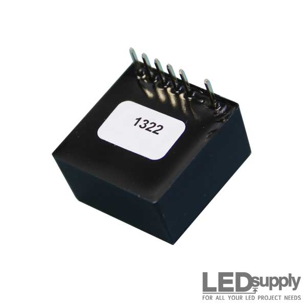
BoostPuck DC Boost LED Driver


More images

Purchase
SAME DAY SHIPPING
- Low-Voltage DC Constant Current Device
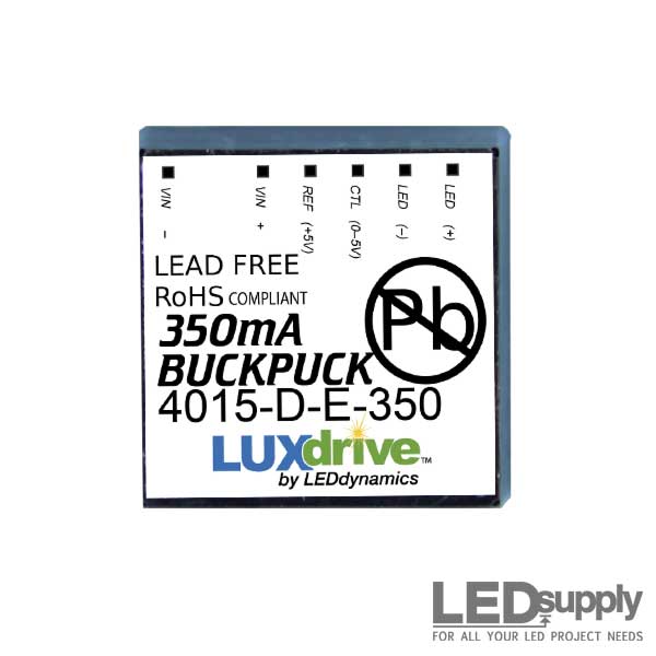
- Current Output: 350mA
- 7-pin SIP Connection (Through-hole)


Product Details
| Output Current (mA): 350mA | Input Voltage Range (DC): 5-28VDC |
| Connection Type: 7-Pin SIP | Compliant: RoHS |
| Dimming: 0-5V | Output Protection: Open Circuit |
| Input Protection: Surge | Small Form Factor: 0.83"(L) X 0.83"(W) X 0.43"(H) |
| Potentiometer Control: 0-100% Intensity | External Control: Analog/Digital Intensity Control (TTL Compatible) |
| Efficiency: 95% | Optional Control: On-Board Trim Adjustment (75-120%) |
Description
The US manufactured LuxDrive™ 4015 series BoostPuck is a, 5-28Vdc, boosting constant current output LED driver for powering high-brightness (HB) LEDs. The intended use for a BoostPuck driver are applications where the forward voltage of LEDs is greater than the input voltage to the BoostPuck. With sufficient current the BoostPuck will 'Boost' the output voltage to meet the requirements of the LED(s).
The BoostPuck contains no lead, is RoHS complaint, extremely low profile, fully potted, and features a 7-pin SIP connection for through-hole PCB mounting or use with an optional wiring harness. Features include optional external dimming and optional on-board trim adjustment as well as standard safety features like, reverse voltage, short and open circuit protection.
Part Numbers, Images & Notes
For specific images and part numbers please select the options and the part number and image will automatically change; more details are included in the specifications and documentation below, but feel free to contact us should you have more questions. If you want to learn more about LED drivers and the selection process there is an informative post on our site, titled: 'Understanding LED Drivers and How To Choose the Right One'.
Technical Documentation
4015 Pinned BoostPuck Product Selection
| Part Number |
DC Input | Output | Control Dimming (V) |
Connection Type |
On-Board Trim 75-120% |
|||||
|---|---|---|---|---|---|---|---|---|---|---|
| Min. (VDC) |
Max. (VDC) |
Input Margin |
Current mA |
Tolerance (±) |
Efficiency (%) |
Max Voltage (V) |
||||
| 4015-D-E-350 | 5 | 28 | -3 | 350 | 10% | 95 | 48 | Yes | 7-Pin SIP (6 Pins) | No |
| 4015-D-I-350 | 5 | 28 | -3 | 350 | 10% | 95 | 48 | Yes | 7-Pin SIP (6 Pins) | Yes |
Absolute Maximum Ratings
| Parameter | Maximum Performance |
|---|---|
| Control Pin, adjustment threshold | 1.5V ±5% |
| Control Pin, shut off threshold | 4.3V ±5% |
| Control Pin, input impedance | 1.8K ohm |
| Reference voltage (Vin=7V or great) | 5VDC ±5% |
| Optional trim pot adjustment range | 75%-120% |
| External pot adjustment range | 0%, 1-100% |
| Maximum flash frequency | 1kHz |
| Minimum Strobe pulse width | 500µs |
| Strobe turn-on / turn-off time | <50µs |
| Quiescent current (no load or control pin high) | <12mA |
| Operating Temperature | -40°C - 85°C |
| Storage Temperature | -40°C - 125°C |
Important Information
The 4015 Wide Range LED Power Module is a high efficiency dc to dc converter which delivers a fixed output current by varying the output voltage as required to maintain the specified current . A fast response current-sensing circuit permits the unit to be used in applications where flashing or pulsing of the LEDs is required. Several options are available allowing for use with many types of LEDs and in a variety of operating modes.
Fixed Current Drive: The fixed output of the 4015 is designed to supply rated current to four to twelve LED junctions connected in series. A single 4015 will drive up to twelve LUXEON I LEDs connected in series. Due to the nature of the boost regulator, the input voltage must always be less (V < V) than the total forward voltage drop of the LED junctions connected in IN series. For example, to drive a string of six junctions having an average forward drop of 3.5V, the forward voltage required for the string is 21V (6x3.5V=21V). The input voltage should be kept at least 3 volts lower than the total forward LED voltage, therefore 18V can be considered the practical maximum. A standard 12V power supply is a good choice for this application.
Adjustable Current - On-Board Control - “I” Model: Where the ability to adjust the output current to an intermediate value is desired, models are available with an on- board potentiometer. This permits the output current to be varied from approximately 75-120% of the rated value while maintaining full external dimming capability. When measuring the output current in order to determine a particular set point, the following method is recommended:
- Temporarily place a 0.1 ohm, 1% resistor in series with the LED+ output.
- Read the voltage across the 0.1 ohm resistor
- The voltage, in millivolts X 10, will equal the output current in mA.
NOTE: Because there is a small, high-frequency component in the 4015 output, many multi-meters will give an incorrect reading when used in the current mode. It has been found that the method previously described yields a far more accurate measurement.
The potentiometers used for the on-board adjustable “I” units are rated for a limited number of rotations (typically 100) and are intended for "set it and forget it" applications. Where frequent adjustments of output current are needed, the use of units with external adjustment capabilities is recommended.
Adjustable Current - External Control - “E” Model: Both the “E” and “I” models feature externally adjustable output current. Figures 6 and 7 show external adjustment configurations. Both use a 5Kohm, linear taper potentiometer. In Figure 6, the potentiometer is connected between the internal 5V reference (Ref) output and the control (Ctrl) input. When using this DC configuration, it is important that Vin be 5.25V or higher. Figure 7 shows the control potentiometer being DC powered by an external 5V source. In either configuration, connect the potentiometer such that clockwise DC rotation increases the resistance. Note that because the current through the potentiometer is less than 5mA, a low power potentiometer may be used.
External On/Off Control: Where a manual on/off control is desired, the potentiometer in Figures 6 and 7 may be replaced by a pushbutton or toggle switch. The output current will be zero when the switch is closed. Figures 8 and 9 show external dimming control combined with on/off control. The circuit in Figure 9 uses a 2N4403 or equivalent PNP switching transistor.
External Pulse/Strobe Control: Figures 10 and 11 show two methods for low speed pulsing or high speed flashing operation. In Figure 10, a TTL/CMOS logic signal is applied directly to the control (Ctrl) input of the 4015. The output current will be zero when the control signal is high. Note that the input needs to source a minimum of 4.75V into a 1Kohm input DC impedance. Also, as is the case with a dc control signal, the logic input ground should to be common to the LED output terminal.
Figure 11 shows an inverted input configuration using a 2N4401 or other NPN switching transistor. In this case, a logic high will cause the output to be "on". In either configuration, the rise and fall times of the output will be 15µsec or less. A pulse frequency up to 1kHz may be used.
Microprocessor Control: Figure 12 shows a typical interface for a microchip PIC or similar micro-controller. The reference output provides the operating voltage for the processor (up to 20mA current).
Other Control Applications: In addition to the configurations described above, the 3021/3023 may also be driven by a D to A converter. As in the cases above, the analog control signal should have its ground common to LED-. Figure 2 shows the efective control range of the analog input signal.
Connections: In all cases, the LEDs being driven should be located as close to the 4015 LED output as possible. When the use of long leads is required, use heavier gauge wire. For strobe or pulse applications, a wire length not exceeding 6" should be used to maintain accurate timing. All control wires should also be less than 6" in length.
Due to the high current draw of the 4015, power input wires/traces should also be kept short. Where DC input units are located more than 6" from the power source, a 220µF, 35V capacitor should be placed across the input terminals as shown in Figure 13.
For applications where the use of header pins is inconvenient, a mating connector with 6" leads is available as an accessory, or the 3023 part number may be used, which is supplied with 6” colored leads.
- 3021HN - Harness for “N” type (4-wire)
- 3021HE - Harness for “E” & “I” type (6-wire)
- 3021HEP - Harness for “E” & “I” w/pot (6-wire w/pot)
Note: The above are product highlights and not the complete manufacturers datasheet. Please view the .pdf for complete specifications.
Full Documentation
Accessories
BoostPuck Accessories:

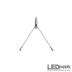
BuckPuck - Wiring Harness with Dimming Wires

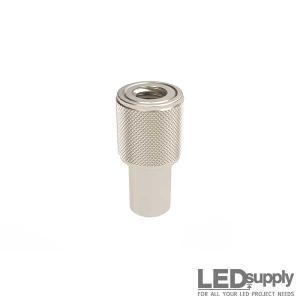
Aluminum Turn Knob

BuckPuck - Wiring Harness with Dimming Wires and Potentiometer

AWG Stranded Wire
Shipping
LEDSupply does NOT profit from the shipping or handling of your order!
Orders received before 3PM EST will be safely packaged and quickly shipped the same business day. If your order is NOT shipped the same business day, LEDSupply will offer a 5% discount off your next order.
All orders SHIP FROM:
296 Beanville Road
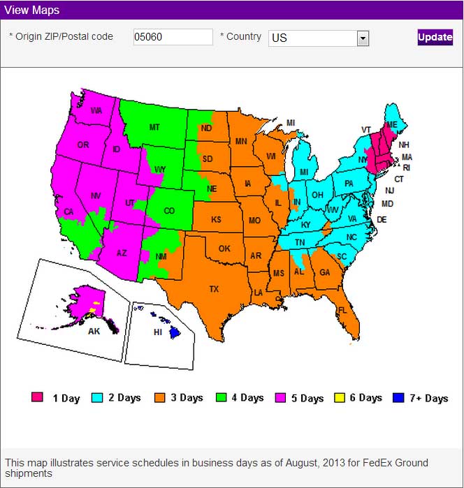
Randolph, Vermont 05060
See respective ZONE maps below for SPECIFIC delivery time to your location:
Any order that does not qualify for free shipping, will by default include a discount of equal value to the free shipping offer.
The shipping offered is meant to provide the widest variety of shipping options at the lowest price:
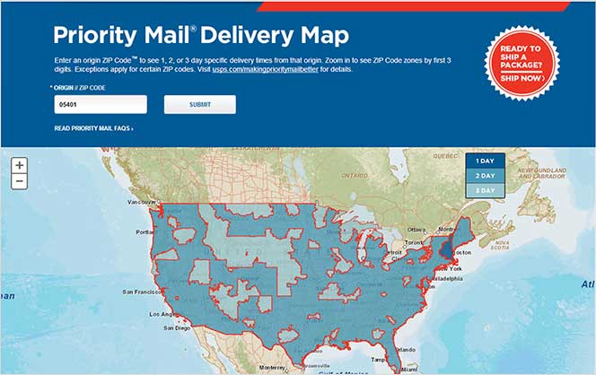
USPS Priority Delivery Zone Map:
FedEX Ground Delivery Zone Map:
UPS Ground Delivery Zone Map:


- Low Prices
- Knowledgeable Support
- 100K+ Orders Shipped
- Free Shipping
- Bulk Discounts
- 2,000+ 5-Star Reviews
LEDSupply is a trusted provider of engineered LED lighting solutions, serving OEMs, integrators, contractors, and lighting professionals with technical expertise, application support, and carefully curated high-performance products. Backed by decades of industry experience, our team helps customers move from components to complete lighting solutions with confidence. Learn More


Shipping
LEDSupply does NOT profit from the shipping or handling of your order!
Orders received before 3PM EST will be safely packaged and quickly shipped the same business day. If your order is NOT shipped the same business day, LEDSupply will offer a 5% discount off your next order.
All orders SHIP FROM:
296 Beanville Road
Randolph, Vermont 05060
See respective ZONE maps below for SPECIFIC delivery time to your location:
Any order that does not qualify for free shipping, will by default include a discount of equal value to the free shipping offer.
The shipping offered is meant to provide the widest variety of shipping options at the lowest price:
- FREE USPS First Class SHIPPING on orders under 13oz & >$49.99
- $5.99 USPS First Class on orders under 13oz & <$49.99
- $15.99 2-Day SHIPPING on orders under 2lbs
- $11.99 GROUND SHIPPING on orders under 2lbs
- $39.99 Standard Overnight SHIPPING on orders under 2lbs
- $49.99 Priority Overnight SHIPPING on orders under 2lbs
- Real-Time Rates are calculated for all International shipments
- *Base Rate + $1.99/lb for orders over 2lbs
USPS Priority Delivery Zone Map:
FedEX Ground Delivery Zone Map:
UPS Ground Delivery Zone Map: